38+ Fakten über Alternator Circuit Explained: Four wires connect the alternator to the rest of the charging system.. S is used by the regulator to monitor charging voltage at the battery. Wiring diagram how an alternator works. P0562 (charging system low voltage). The working principle of an alternator is very simple. The alternator has a rotor that spins when the engine cranks.
Alternators have replaced dynamos as generators on modern cars; Never make or break any connection while the engine is running. Alternators produce alternating current through a process known as electromagnetism. For reasons of cost and simplicity, most alternators use a rotating magnetic field with a stationary armature. The acu also monitors main bus voltage and activates the low volts annunciator below approximately 24.5 volts.
3 Wire Nissan Alternator Wiring Diagram Novocom Top from i1.wp.com Alternators that have one positive wire connected to the alternator has the ground connected to its case. The acu adjusts the alternator field current to regulate alternator output, supplying the main bus with approximately 28.5 volts. Alternators produce alternating current through a process known as electromagnetism. Ig is the ignition input that turns on the alternator/regulator assembly. If the ecm senses a charging voltage below 11v for at least 1 minute. Honda alternator and charging systems explained. The alternator has a rotor that spins when the engine cranks. Opening the alternator reveals a large cylinder with triangular finger poles around the circumference.
Honda alternator and charging systems explained.
B is the alternator output wire that supplies current to the battery. The alternator has a rotor that spins when the engine cranks. Alternators have replaced dynamos as generators on modern cars; All cars with an internal combustion engine except for some hybrids have an alternator. As the rotor turns within the stator windings, the magnetic field of the rotor sweeps through the stator windings, producing an electrical current in the windings. Never make or break any connection while the engine is running. Wiring diagram also offers helpful recommendations for tasks that may require some additional equipment. Any short or open circuit or wrong connection can cause a sudden surge of voltage that will damage electronic parts. Units, the benefits of fitting a modern alternator with its much simpler circuit after a failure, will outweigh the cost. There is another circuit in the alternator to control the charging system warning lamp that is on the dash. A voltage regulator converts the power generated by the alternator to direct current. Because of the rotation of the rotor, an alternating current is produced. The diode trio takes current coming from the three stator windings and passes a small amount through three diodes so that only the positive.
Because of the rotation of the rotor, an alternating current is produced. For understanding working of alternator let us think about a single. Wiring diagram also offers helpful recommendations for tasks that may require some additional equipment. Opening the alternator reveals a large cylinder with triangular finger poles around the circumference. Units, the benefits of fitting a modern alternator with its much simpler circuit after a failure, will outweigh the cost.
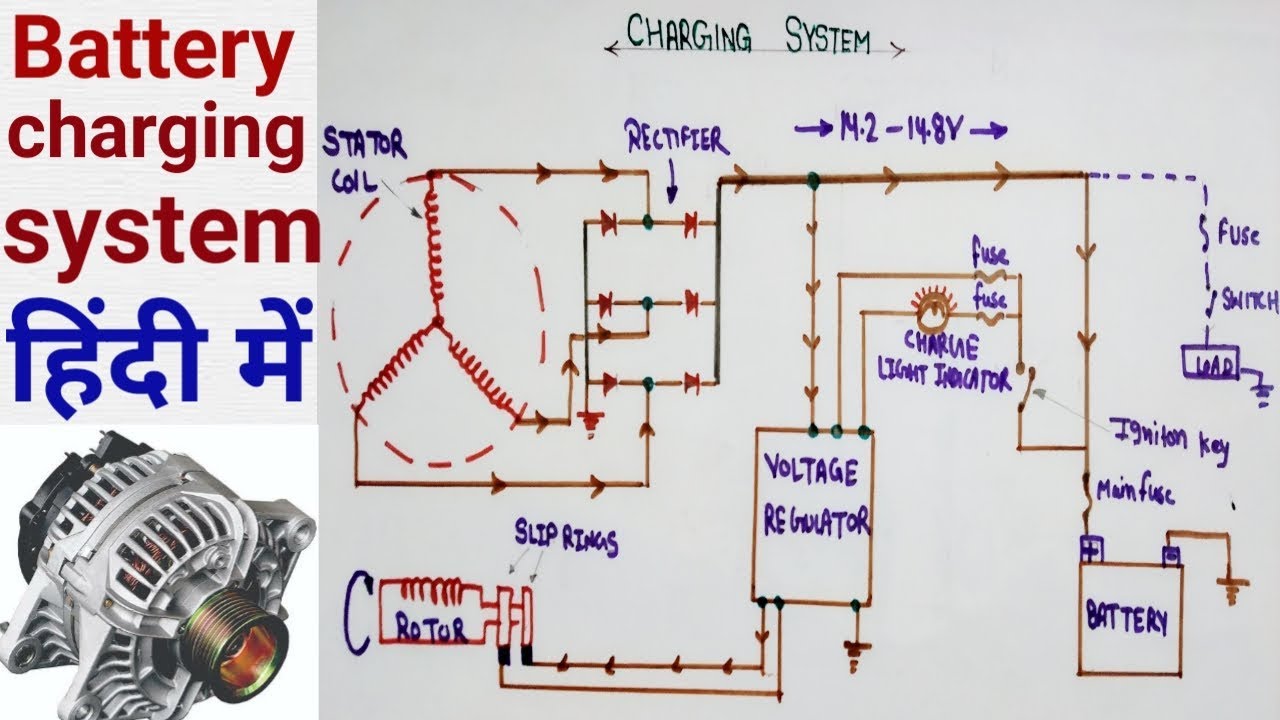
Alternator Circuit Diagram Battery Charging System Components Of Alternator In Hindi Youtube from i.ytimg.com All cars with an internal combustion engine except for some hybrids have an alternator. The basic operation is as described below, except the alternator only uses 6 diodes and has an external regulator and energisation circuit. Alternators have replaced dynamos as generators on modern cars; The acu adjusts the alternator field current to regulate alternator output, supplying the main bus with approximately 28.5 volts. The voltage regulator controls system voltage by controlling the electrical circuit (called the field circuit) that energizes the electromagnet of the alternator rotor. It controls the amount of voltage provided by the alternator to maintain a constant voltage to the battery and electrical equipment in your vehicle, as the name suggests. Wiring diagram also offers helpful recommendations for tasks that may require some additional equipment. A basic alternator is made up of a series of alternating finger pole pieces placed around coil wires called field windings that wrap around an iron core on the rotor shaft.
An alternator works with the battery to supply electricity to components of a vehicle.
General overview of how an alternator works.how an automotive alternator works tutorial autoshop 101. Units, the benefits of fitting a modern alternator with its much simpler circuit after a failure, will outweigh the cost. Because of the rotation of the rotor, an alternating current is produced. The alternator has a rotor that spins when the engine cranks. The following information is presented as a guide when wiring and troubleshooting alternators. Alternator, how it works, symptoms, testing, problems, replacement. The acu adjusts the alternator field current to regulate alternator output, supplying the main bus with approximately 28.5 volts. A basic alternator is made up of a series of alternating finger pole pieces placed around coil wires called field windings that wrap around an iron core on the rotor shaft. 12 volt alternator installation operation manual introduction thank you for choosing a balmarr high output alternator. Part of that circuit is another set of diodes mounted inside the alternator called the diode trio. The alternator has a rotor that spins when the engine cranks. The diode trio takes current coming from the three stator windings and passes a small amount through three diodes so that only the positive. The stator is fixed to the shell of the alternator, and does not turn.
Alternator, how it works, symptoms, testing, problems, replacement. The working principle of an alternator is very simple. Never make or break any connection while the engine is running. Ig is the ignition input that turns on the alternator/regulator assembly. It is just like the basic principle of dc generator.it also depends upon faraday's law of electromagnetic induction which says the current is induced in the conductor inside a magnetic field when there is a relative motion between that conductor and the magnetic field.
Me08 from www.tb-training.co.uk Wiring diagram how an alternator works. Units, the benefits of fitting a modern alternator with its much simpler circuit after a failure, will outweigh the cost. The acu also monitors main bus voltage and activates the low volts annunciator below approximately 24.5 volts. The alternator in your car is a kind of mini electrical generator, which converts mechanical energy into electrical energy through a process known as alternating current. Aktuelle preise für produkte vergleichen! For reasons of cost and simplicity, most alternators use a rotating magnetic field with a stationary armature. A voltage regulator alternator is a vital part of the charging mechanism of your vehicle. The alternator has a rotor that spins when the engine cranks.
Alternators that have one positive wire connected to the alternator has the ground connected to its case.
The basic operation is as described below, except the alternator only uses 6 diodes and has an external regulator and energisation circuit. Any short or open circuit or wrong connection can cause a sudden surge of voltage that will damage electronic parts. The alternator in your car is a kind of mini electrical generator, which converts mechanical energy into electrical energy through a process known as alternating current. The excitation system is responsible for supplying the field current to the main rotor. The stator is fixed to the shell of the alternator, and does not turn. Honda alternator and charging systems explained. When an engine is running, the alternator charges the battery and supplies. B is the alternator output wire that supplies current to the battery. For reasons of cost and simplicity, most alternators use a rotating magnetic field with a stationary armature. Without an alternator, the engine in your car would have no spark, your headlights no light, and your heater no way to keep you comfortable in the winter. As the rotor turns within the stator windings, the magnetic field of the rotor sweeps through the stator windings, producing an electrical current in the windings. The following information is presented as a guide when wiring and troubleshooting alternators. Never make or break any connection while the engine is running.